A topic which has sparked a lot of conflicting opinions is the use of DC isolators within solar installations, specifically between the PV panels and the electronic equipment.

In this guide we will take a look at the information provided to us by the wiring regulations and IET code of practices to see if we can de-bunk the opinions flying around on the ever opinionated social media platforms.


What the British Standard 7671 Wiring Regulations say regarding DC Isolation?

712.537 Isolation and switching

712.537.2 Isolation

712.537.2.101 To allow maintenance and replacement of the inverter, means of isolating the inverter from the DC side and the AC side shall be provided.

712.537.2.2 Devices for isolation

712.537.2.2.101 A switch disconnector or a circuit-breaker suitable for isolation shall be provided on the DC side of the inverter.

Our tiny build systems and components are slightly different to the above mentioned by BS7671. That’s because these regulations are aimed specifically towards PV installations in domestic, commercial and industrial applications that use a solar inverter to convert the DC into AC straight away rather than a solar charge controller and battery setup.

A solar inverter is not to be confused with the type of inverters we commonly use to supply 230V items in our campervans. A Solar Inverter is a device that converts direct current (DC) electricity, which is what a solar panel generates, to alternating current (AC) electricity, which the electrical grid uses. These units often have double pole isolators built into them, therefore mitigating the requirement for a external DC isolator.

Due to the regulations not mentioning anything regarding MPPT Solar Charge Controllers (DC/DC) it therefore leaves us with no other choice as designers than to assume worst case scenario and to include a means of isolation.

Solar Inverter
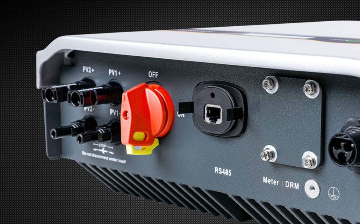
A Solar Inverter with built in DC Isolator. Commonly used in Domestic applications.

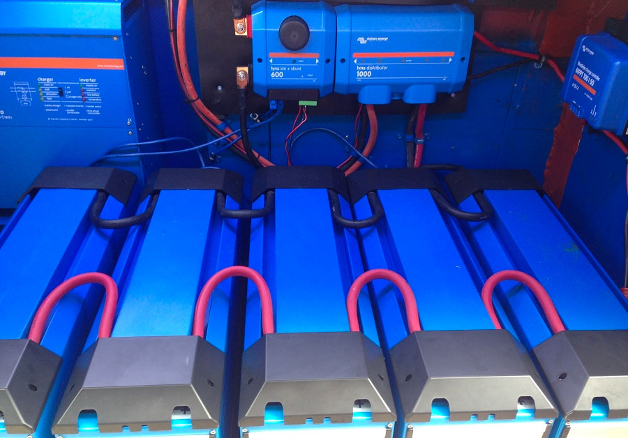
If the MPPT controller was in need of replacement or maintenance, the DC supply from both the battery and solar panels would need to be isolated in order for the system to be considered ‘safely isolated’. The easiest way to isolate these supplies would be via isolators.

So BS7671 is very clear in that it states you do require a DC isolator in order to isolate the DC supply, but it only specifically mentions inverters with no mentioned of charge controllers or any other electronic devices.

DC Isolator
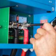
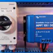
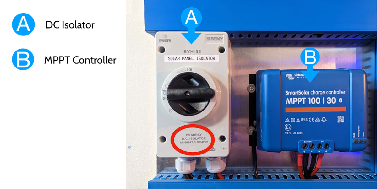
A Tiny Build Electrics installation using a DC Isolator, conforming to 60947-3, to isolate the solar panels from the rest of the installation.

IET Code of Practice – Grid Connected Solar Voltaic Systems

The IET Code of Practice guide gives us a little bit more information and slightly less ambiguity when it comes to our solar installations within our campervans, motorhomes and tiny builds. This code of practice is specifically looking at Grid Connected Systems, and although campervans and motorhomes have stand alone, off-grid systems, they
often connect to the grid via the shore power inlets which then makes them a grid connected system and therefore
this code of practice does certainly have relevance when referring to their installations.

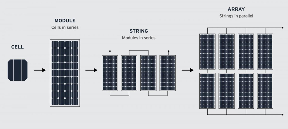
Before looking at the table provided by the IET Code of Practice its worth noting the definitions of the below:

PV String – When modules are connected in series fashion, this forms a string. In a string, the voltage adds up though the current remains the same.

PV Array – When modules are connected in series and parallel fashion, this forms an array. In an array, the current adds up when connected in parallel and the voltage adds up when connected in series.
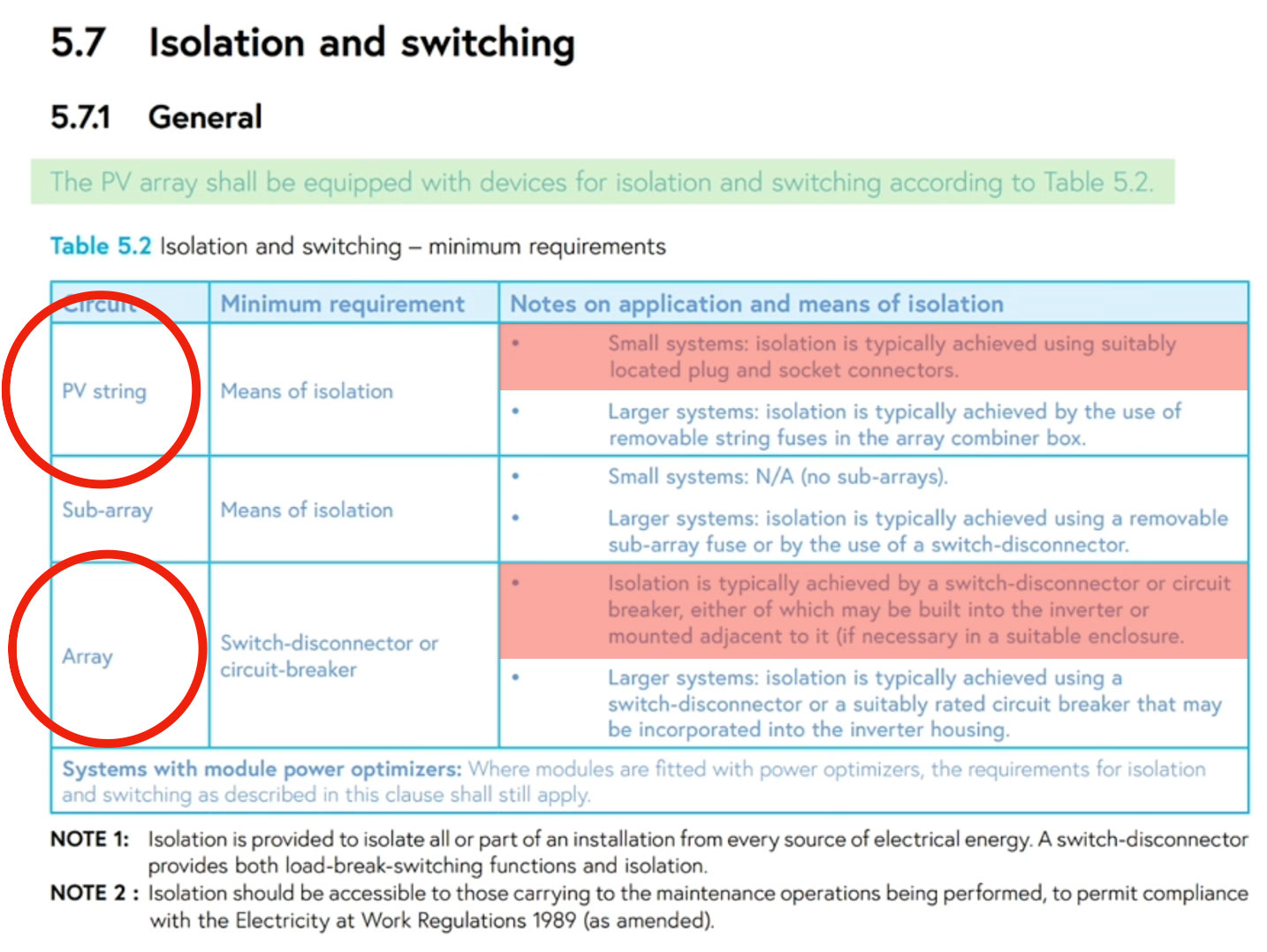
Module

Codes of Practice

1. PV StringThe minimum requirement as a means of isolation for small systems is typically achieved using suitably located plug and socket connectors.

Referring back to the definitions above, it seems that most campervan and motorhome PV installations can be considered a string due to the small number of panels and systems being commonly wired in series, therefore according the the ‘Notes on application and means of isolation’ section, technically do not require an isolator or switch disconnecter.

In this instance, a MC4 connector, which is deemed as a ‘suitable plug and socket connector’, will be sufficient. Just remember that this is a minimum requirement and for both safety and practicality, we still recommend DC isolators for all of our systems.

The main reason that we at Tiny Build Electrics do not advocate using the MC4 connector as a method for isolation is that the connectors must be located in an area that is practical and accessible. The roof of the campervan, where most MC4 connectors are located on campervans and motorhomes, is neither practical or readily accessible.

2. ArrayIsolation is typically achieved by a switch-disconnecter or circuit breaker, either of which may be built into the inverter or mounted adjacent to it. (if necessary in a suitable enclosure).

Once again, referring to the definitions above a parallel connected set of modules (solar panels) would arguably be noted as an array and therefore requires isolation on the DC side. According to note above set out by the IET

‘Isolation is typically achieved by a switch-disconnecter or circuit breaker.’

Diagram
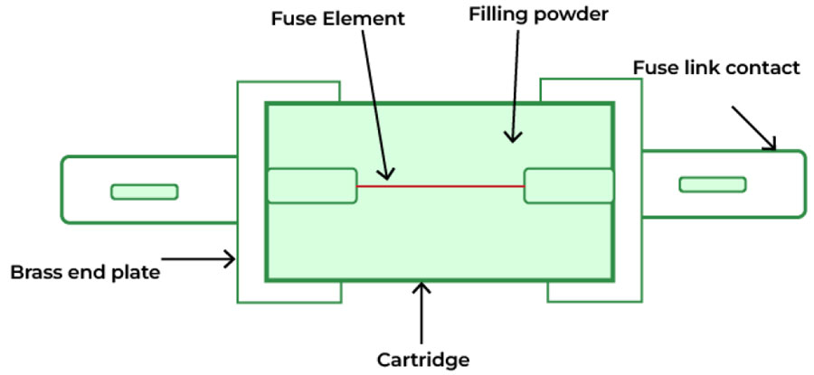
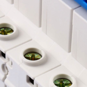
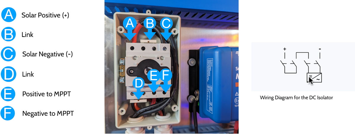
The inside of a DC isolator used to isolate solar panels in a campervan’s electrical system

Table 537.4 – Guidance on the section of protective, isolation and switching devices

Table

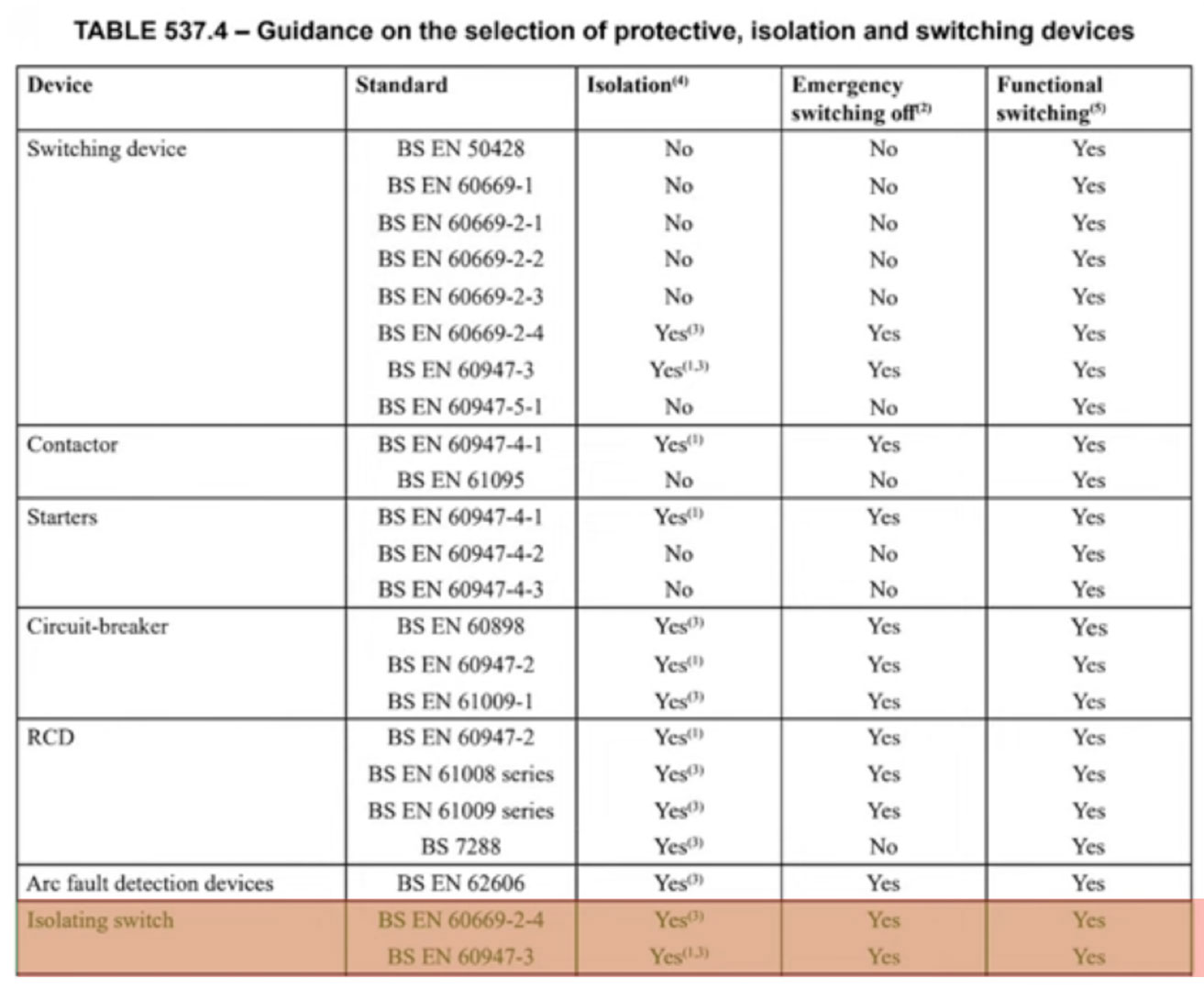
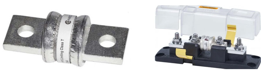
We at Tiny Build Electcrics always recommend that you use an isolator, irrespective of your solar panel setup. The isolator used to isolate your PV panels must meet the British Standards set out in the table above.

The isolator must comply with BS EN 60669-2-4 and/or BS EN 60947-3 in order to be compliant with the British Wiring Regulations.


Do the above code of practices and regulations take campervans and motorhomes into consideration?

The best practices and regulations mentioned above do not specifically take campervans and motorhomes into consideration but that does not mean we can’t use the information provided to be compliant and ensure our installations are not only meeting the minimum requirements but going above and beyond to be safe.

BS7671 Section 721, Electrical installations in caravans and motor caravans focus directly on the electrical systems within motor caravans. This section merely notes the deviations from the rest of BS7671, so we’re seemingly left to read between the lines here.

The likelihood of a solar panel or solar charge controller getting damaged and/or needing maintenance in a campervan or motorhome is higher than in a house or building which do not move, vibrate, or get driven down a bumpy old track to get to the best surf location! This is one of the key reasons to install an isolator.


Argument against DC Isolators

An argument against DC isolators is that they cause a resistance in the solar panel cables and therefore reduce the current carrying capacity of the cable and as a result the output from the MPPT solar charge controller could suffer and will therefore be unable to produce the optimum charge current. Although this has some truth, the way in which the cables are terminated into the isolator plays a big part in reducing the resistance.

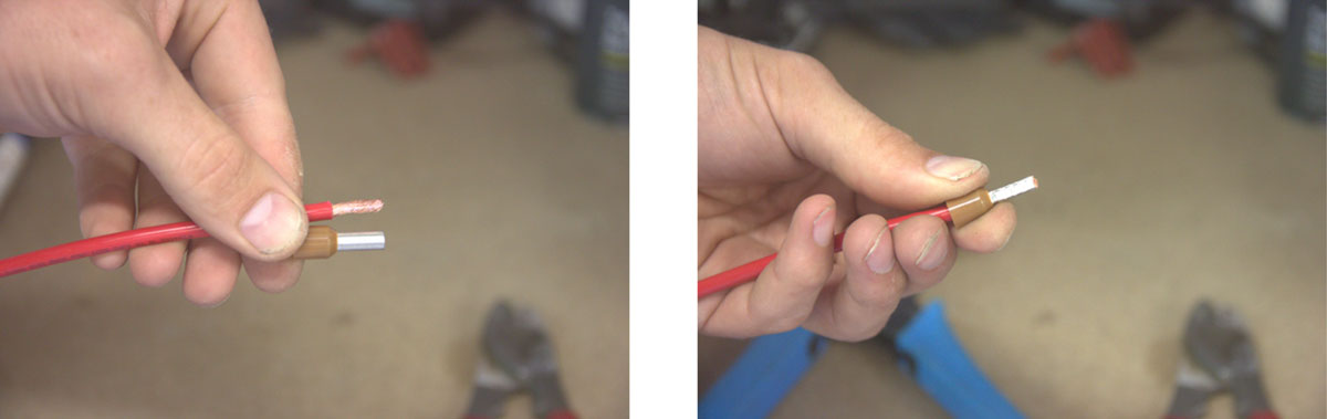
In most installations we see the multi stranded cable coming from the solar panels have been twisted together and poorly terminated into the contacts of the DC isolator. The strands are either damaged and/or missing, caused by pressure put on the cores when stripping away the cable’s insulation.

The use of ferrules here is paramount as it contains all the strands into one ferrule which not only makes a better contact within the isolator, but also makes it easier for the installer to locate the cable in the terminal.

Wires

Conclusion

We at Tiny Build Electrics approach this with a ‘belt and braces’ method way of thinking and always insist a DC isolator be present between the solar panels and the solar charge controller.

Should the solar charge controller need isolating for maintenance or replacement, one flick of the isolator and the MPPT is safely isolated from the solar panels. Having to disconnect MC4 connectors, whether placed on the roof or in a cupboard, is more leg work and not deemed as safe.

LiFePO4 fuse selection – Class-T, MRBF, and MEGA

Reliable electrical systems are essential for mobile, marine, and off-grid applications. One crucial part of a reliable electrical system is system safety. Fuses provide critical overcurrent protection, safeguarding equipment and preventing fire hazards.

This guide focuses specifically on LiFePO4 (Lithium Iron Phosphate) battery systems and details the characteristics of Class-T, MRBF, and MEGA fuses, assisting in proper selection for these high-performance battery chemistries.

Lithium Iron Phosphate Batteries

Important Note: This guide is exclusively directed at LiFePO4 battery systems. LiFePO4 batteries possess significantly lower internal resistance compared to lead-acid or AGM batteries. This characteristic allows them to deliver exceptionally high short-circuit currents, making proper fuse selection absolutely critical. While fuse selection remains important for lead-acid and AGM systems, the potential for extremely high fault currents is considerably lower due to their inherently higher internal resistance. The recommendations in this guide are not necessarily applicable to lead-acid or AGM battery systems.

The Importance of correctly selecting the right fuse for LiFePO4 electrical system

Fuses are designed as the weakest link in a circuit, interrupting current flow during overloads. When looking at LiFePO4 batteries, the potential for rapid and substantial short-circuit currents necessitates careful fuse selection. Incorrect fuse selection can lead to premature failures, or more dangerously, inadequate protection, potentially causing catastrophic damage or fire. A properly rated fuse is crucial for safety and system reliability in LiFePO4 systems.

Battery Diagram

Fuse Types: Class-T, MRBF, and MEGA

Class-T Fuses:

These fuses handle high-current applications common in inverters, battery banks, and critical power circuits. Their high interrupting capacity (AIC) allows them to safely interrupt substantial fault currents, crucial in LiFePO4 systems with large battery banks. Class-T fuses are typically bolt-on and require compatible holders.

Fuses

MRBF Fuses (Marine Rated Battery Fuse):

Designed for marine environments, MRBF fuses offer corrosion and vibration resistance. Their compact size and direct battery terminal mounting are advantageous in space-constrained installations. While typically used in marine applications, MRBF fuses are also perfectly suitable for other applications like campervans and motorhomes where space and a secure connection directly to the battery terminal are beneficial. They also provide relatively fast-acting protection.

Fuses

MEGA Fuses:

Bridging the gap between smaller automotive fuses and larger Class-T fuses, MEGA fuses are common in automotive and recreational vehicle (RV) applications. They protect high-current circuits like charging systems, alternators, and starter motors. It’s important to note that MEGA fuses typically have a lower AIC rating (around 2000A or 2kA) compared to MRBF or Class-T fuses.

Fuses

Tiny Build Electrics’ Recommended AIC Sizing Protocol for LiFePO4 Batteries

At Tiny Build Electrics, we prioritise safety and recommend a specific protocol for determining the appropriate Ampere Interrupting Capacity (AIC) for your fuses in LiFePO4 systems. Due to the inherent characteristics of LiFePO4 batteries, AIC selection is paramount.

Batteries

Tiny Build Electrics Rule of Thumb (LiFePO4 Only): We advise allowing 5000A of AIC for every 100Ah of LiFePO4 battery capacity.

Calculation Breakdown:

1. Determine Battery Bank Capacity: Identify the total Amp-hour (Ah) capacity of your LiFePO4 battery bank.
2. Calculate Required AIC: Multiply your battery bank’s Ah capacity by 50. This gives you the recommended AIC in Amperes.
3. Select Fuse Type: Choose a fuse with an AIC rating equal to or greater than the calculated value.

Breakdown

Examples (LiFePO4 Only):

100Ah LiFePO4 Battery:

100Ah * 50 = 5,000A AIC. A MEGA fuse, with its limited 2,000A AIC, is not sufficient for this application. An MRBF or a Class-T fuse would be required.

100Ah LiFePO4 Battery

200Ah LiFePO4 Battery:

200Ah * 50 = 10,000A AIC. An MRBF fuse, with a 10,000A AIC rating, would be appropriate.

200Ah LiFePO4 Battery

2X 200Ah LiFePO4 Batteries in Parallel (400Ah Total)

400Ah * 50 = 20,000A AIC. It is crucial to use a separate fuse for each battery in a parallel configuration. In this example, you would install two MRBF fuses, one for each 200Ah battery, even though the total AIC requirement is 20kA. This is because each battery could independently deliver a short-circuit current of 10,000A.

200Ah

300Ah LiFePO4 Battery:

300Ah * 50 = 15,000A AIC. A Class-T fuse, offering a 20,000A AIC rating, is the recommended choice due to its higher AIC capacity.

300Ah

Important Considerations for LiFePO4 Systems:

1. Always consult the fuse manufacturers specifications: Ensure the selected fuse’s voltage rating is appropriate for your system.

2. Consider other circuit characteristics: The AIC calculation is a guideline. Factors like cable length and other components can influence the actual short-circuit current.

3. This guide is ONLY applicable to LiFePO4 systems: The very high short circuit currents possible with LiFePO4 necessitate this specialised guidance.

4. MEGA Fuse Limitations: Due to their lower AIC rating, MEGA fuses are generally not recommended for direct connection to larger LiFePO4 battery banks. They might be suitable for protecting specific high-current circuits branching off the main battery bank, but only if the calculated AIC for that specific circuit is within the MEGA fuse’s rating.

5. When in doubt, consult a professional: Electrical system design and safety are critical, especially with LiFePO4 batteries. If you’re unsure about fuse selection, seek advice from a qualified electrician or marine electrical specialist.

Professional Consultation Recommended

Correct LiFePO4 fuse selection and installation are critical for electrical system safety, especially with the high-current potential of LiFePO4 batteries. Consulting a qualified electrician or marine electrical specialist is highly recommended. Proper fuse selection is a crucial investment in safety and system reliability.

Miniature Circuit Breakers (MCBs) are indispensable devices in electrical systems, offering protection against overcurrents and short circuits. These compact devices are particularly vital for campervan electrical systems, where limited space and safety considerations play crucial roles. 

In this article, we will explore what MCBs are, how they work, and how they can be implemented effectively in campervan electrical systems. Additionally, we’ll discuss two different types of MCBs and decipher the codes associated with them.

Understanding Miniature Circuit Breakers

Miniature Circuit Breakers are automatic electrical switches designed to protect electrical circuits from damage caused by excessive currents. They serve as vital safeguards, preventing overloads and short circuits that could potentially lead to fires or damage to sensitive equipment.

Functioning of MCBs

The primary function of an MCB is to interrupt the flow of current when it exceeds a predetermined threshold. They consist of a switch mechanism and a bimetallic strip or an electromagnetic coil. When the current exceeds the rated limit, the bimetallic strip heats up and bends, causing the switch to trip and disconnect the circuit. In the case of an electromagnetic coil, a magnetic field is generated when the current exceeds the set limit, tripping the switch. This quick response time ensures the protection of the electrical system.


Campervan MCB Selection For Your Electrical System

Campervans have limited space, making MCBs an ideal choice due to their compact size. Here are some considerations for MCBs selection in your campervan electrical systems:

Load Calculation: Begin by calculating the anticipated electrical load of each circuit. This includes appliances, lighting, heating, and any other A/C electrical devices you plan to install. This calculation will help determine the appropriate ampere rating for the MCBs.

Circuit Design: Designate circuits based on the electrical load calculations, grouping similar devices together. For example, sockets should be on a separate circuit from the hot water tank to avoid overloading.

MCB Selection: Choose MCBs with appropriate ampere ratings for each circuit. Ensure they are compatible with the electrical system voltage. Typical MCB ratings for campervan applications range from 6A to 16A.

Selecting a Circuit Breaker Based On The Following:

  • The circuit breaker construction standard, BS EN 60898
  • Current rating for overload protection, with preferred values: 6 A, 10 A and 16 A.Rather than go to 16 A, however, the designer would be better specifying more circuits at 10 A, or even 13 A.
  • Sensitivity for fault protection, with Type B or Type C; but NEVER Type D
  • Short-circuit capacity – probably between 3000A (3kA) and 6000A (6kA)
  • Energy limiting class – preferably 3
  • That the circuit breaker must disconnect both line and neutral conductors (2-pole), to satisfy Regulation 721.43.1 of BS 7671 for touring caravans and motorhomes.

721.43.1 Final circuits: Each final circuit shall be protected by an overcurrent protective device which disconnects all live conductors of that circuit.

Double Pole Miniature Circuit Breakers

As we have highlighted above in the last bullet point, circuit breakers used for the protection of circuits in touring caravans and motorhomes must be double-pole, including the main disconnector/main switch. (Regulation 721.537.2.1.1 of BS 7671). 

721.537.2.1.1 Each installation shall be provided with a main disconnector which shall disconnect all live conductors and which shall be suitably placed for ready operation within the caravan. In an installation consisting of only one final circuit, the isolating switch may be the overcurrent protection device fulfilling the requirements for isolation. 

Some confusion lies here for installers and van builders as the obvious choice is a single-pole device, making and breaking the line conductor only. 

Since a touring caravan or motorhome is considered a special location by the IET wiring regulations, we are to adhere to slightly stricter guidelines. A double pole overcurrent protection device being one of them. 

Since owners of motorhomes and caravans are likely to travel to countries where polarity of supply is not as rigorously enforced as the UK, the designer will want to specify 2-pole devices providing protection for both the line and neutral conductors. 


Types of MCBs and Alphanumeric Codes:

Type B MCBs: These are the most common MCBs used in residential and commercial applications. They provide protection against overloads and short circuits caused by general-purpose equipment. The alphanumeric code for Type B MCBs starts with the letter “B.”

Type C MCBs: These MCBs offer increased protection for circuits with equipment that have a higher inrush current, such as motors or transformers. The alphanumeric code for Type C MCBs starts with the letter “C.”

Understanding MCB Markings

MCBs are labeled with letters and numbers that provide vital information about their specifications. Let’s decode these markings:

  • Current Rating (In Amperes): This indicates the maximum current that an MCB can handle without tripping.
  • Trip Curve: The letter associated with an MCB (e.g., B or C) denotes its trip curve, which indicates the response time of the circuit breaker to an overload or short circuit.
  • Breaking Capacity: Represented in kiloamps (kA), this value signifies the maximum fault current that an MCB can safely interrupt without causing damage. Typically 6kA (6000a) or 10kA (10,000a). 

How do Miniature Circuit Breakers Work?

MCBs operate based on the principle of thermal and magnetic tripping. They consist of a bimetallic strip and an electromagnet, which respond to different types of electrical faults:

Thermal Tripping: The bimetallic strip within the MCB is designed to heat up when the current flowing through it exceeds the rated value. As the temperature rises, the strip bends and eventually trips the circuit breaker, disconnecting the circuit. This mechanism protects against overloads.

Magnetic Tripping: In the presence of a high magnitude short-circuit current, the electromagnet within the MCB generates a magnetic field. This magnetic field rapidly pulls the trip mechanism, causing the circuit breaker to trip. Magnetic tripping provides rapid protection against short circuits.

The combination of thermal and magnetic tripping ensures that MCBs can respond to a wide range of electrical faults, thereby safeguarding the connected circuits and devices.

*Can’t find miniature circuit breakers in our online shop? That’s because all of our 230V distribution boards are built in house by competent, qualified personnel, to your specific needs, enhancing safety and ensuring that you are being matched with the correct product for your installation.  

Get in contact today and we’ll be happy to size and design your board. 

Cable Terminal

Integration of MCBs into Distribution Boards:

Distribution boards, also known as consumer units or fuse boxes, are key elements in electrical installations. They provide a centralised location for housing MCBs and other protective devices, enabling efficient power distribution and electrical system control.

Mounting: MCBs are mounted onto DIN rails within the distribution board. DIN rail mounting allows for easy installation, removal, and replacement of circuit breakers.

Circuit Configuration: MCBs in distribution boards/consumer units are typically organised to cater to various circuits in the campervan. Each MCB is connected to a specific electrical circuit, such as power outlets, or specific appliances. This arrangement allows selective disconnection of individual circuits in case of a fault, minimising downtime and ensuring safety.

Circuit Identification: To simplify maintenance and troubleshooting, MCBs in distribution boards are labeled or numbered to correspond with the connected circuits. This labelling helps electricians and campervan owners quickly locate and address any issues.

Additional Protection: In addition to MCBs, distribution boards may incorporate other protective devices such as residual current devices (RCDs). These devices provide additional protection against electrical shocks and ground faults, enhancing overall electrical safety. 

Read more about RCD’s and choosing the correct type here.


Regulations

The regulations specify the selection and coordination of MCBs to ensure proper protection against overcurrents. They outline the maximum permitted Zs (impedance of the circuit) values for different types of MCBs, taking into account various factors like cable size, protective device characteristics, and fault currents.

The Wiring Regulations also address issues related to discrimination, which is the ability to isolate a faulty circuit without affecting the supply to other circuits. Discrimination ensures that only the circuit experiencing the fault is disconnected, minimising disruption to the rest of the electrical installation. MCBs should be selected and coordinated in such a way that discrimination is achieved.

Furthermore, the regulations emphasise the importance of proper installation, labelling, and periodic testing of MCBs to maintain their effectiveness. Qualified electricians are responsible for ensuring compliance with the Wiring Regulations and conducting the necessary inspections and tests.

Need help with understanding the regulations surrounding Miniature Circuit Breakers? 

Contact us here at Tiny Build Electrics and we will be happy to help. 


Conclusion

Miniature Circuit Breakers are vital components of electrical installations. They protect circuits and electrical equipment from overcurrents and short circuits, mitigating the risk of fires and damage. 

By understanding the different sizes of MCBs and adhering to the regulations outlined in the British Standard 7671, you can ensure the safe and effective operation of electrical systems.

Remember, when dealing with electrical installations, it is essential to consult with qualified electricians who are knowledgeable about the regulations and possess the necessary expertise to install and maintain MCBs in compliance with the requirements outlined in the Wiring Regulations. 

Safety should always be the top priority in any electrical project, and we at Tiny Build Electrics can help you achieve just that. Contact us for a consultation and we’ll be happy to help. 

Recent updates to BS7671 wiring regulations mean that choosing the correct RCD for a campervan electrical system is more important than ever. In particular, the decline of Type AC RCDs and the shift toward Type A protection has major implications for safety and compliance.

British Standard 7671 wiring regulations state: ’RCD Type AC shall only be used to service fixed equipment where it is known that the loads current contains no DC components’

Both the self and professional builder need to ensure that they are adhering to this regulation otherwise they could be leaving themselves open to using or supplying the incorrect components which can potentially result in an RCD that is unable to trip under fault conditions.

In this article we will delve into the type of RCD you should be using in your camper vans electrical installation. The type of RCD you choose has a detrimental effect to the safety of your system so this is a really important guide to help you through this process.

Types of RCD

There are two main types of RCDs:

1. Type AC: This type of RCD is designed to protect against AC fault currents only. It detects and disconnects the circuit when there is a difference in the current flowing through the line (live) and neutral conductors, which may be caused by a fault to earth. Type AC RCDs are commonly used in domestic and similar installations where the risk of DC faults is low.

2. Type A: This type of RCD is designed to protect against both AC and DC fault currents. It can detect and disconnect the circuit when there is a difference in the current flowing through the line and neutral conductors, as well as when there is a fault current to earth caused by a DC component. Type A RCDs are commonly used in industrial and commercial installations where the risk of DC faults is higher.

In addition to these two main types, there are also other types of RCDs available, including:

3. Type B: This type of RCD is designed to protect against AC, pulsating DC and smooth DC fault currents. It is commonly used in medical locations and locations where the electrical supply is generated from a renewable energy source.

4. Type F: This type of RCD is designed to protect against AC and DC fault currents, including high-frequency DC residual currents. It is commonly used in locations with electronic equipment and installations with frequency converters.

5. Type B+: This type of RCD is designed to provide additional protection against DC fault currents, including those caused by high-frequency ripple currents. It is commonly used in installations with electronic equipment and renewable energy sources.

Wave

IMPORTANT NOTE:

If you intend on buying a consumer unit from a wholesaler then it could be possible that the unit will be supplied with a type AC RCD. Why? Well it is the cheapest model of RCD available, but, this does not provide the correct level of protection for an electrical system containing DC electronics.

Be assured, if you purchase a consumer unit for your campervan via our Tiny Build Electrics store, the unit will come supplied with the correct type A RCD.

Buy Now

How an RCD operates

A residual current device constantly measures the current balance between the line and neutral conductors. The device will open its contacts (trip) if it detects an imbalance between the two conductors.

In a safe, operational system the supply and return current are balanced and therefore no current is leaking to earth. RCD’s are designed to prevent electrocution by detecting the earth leakage and disconnecting the supply before it causes any harm.

RCDs are designed to prevent electrocution by detecting this leakage current, which can be far smaller than the currents that are needed to trip conventional circuit breakers or fuses (several Amperes). RCDs are intended to operate within 25 – 40 milliseconds. This time is faster than the time needed for the electric shock to drive the heart into ventricular fibrillation, the most common cause of death through electric shock. A safe system is a system that protects against short-circuit, overload and earth leakage currents.

Phase

Why Type AC RCD’s are becoming obsolete

Type AC RCD’s have worked perfectly well in the past because the loads put through the RCD were simple resistive loads with very little in the way of electronics. However, as time has gone on systems are becoming ever more sophisticated with a larger amount of electronics present. Loads with DC electronics within them have a nasty habit of leaking DC electricity down the line into our AC network and then on into the RCD.

This DC current has the potential to leak into the type AC RCD and ‘stun’ it, stopping it from tripping when an earth fault occurs. As that’s what an RCD is designed to do, this causes a massive issue. This therefore means the fault will not clear and cause damage to the installation and worse, the user.

This therefore means that a type AC RCD is no longer suitable for many installations, especially camper vans with inverters, battery chargers and other DC operated electronics.

RCD

Which RCD do I need for my campervan?

We recommend that you fit a Type A double pole RCD in your camper vans electrical distribution board. Type A RCDs are specifically designed to detect alternating current (AC) residual currents with a sinusoidal waveform, such as those produced by electronic devices with switching power supplies or equipment with variable speed drives. These types of electrical loads can produce harmonic currents that can be difficult for Type AC RCD’s to detect, making Type A RCDs an important safety measure in many any electrical system containing DC electronics.

Do you need help specifying which RCD you should use? Get in contact with us here!

We at Tiny Build Electrics will not only design and specify your consumer unit, RCD and circuit breakers, but will also build the equipment before its sent out to you. Get in touch and we will be happy to help!