When designing and installing an electrical system in a campervan safety should be at the forefront of everything we do. From correctly sized fuses and cables to correctly terminated outlets this all comes together to create something usable and safe.
When I think of safety in and around campervan electrical systems, my mind instantly diverts to earthing and bonding. These are key safety features and are fundamental to a correctly operating and safe electrical system.
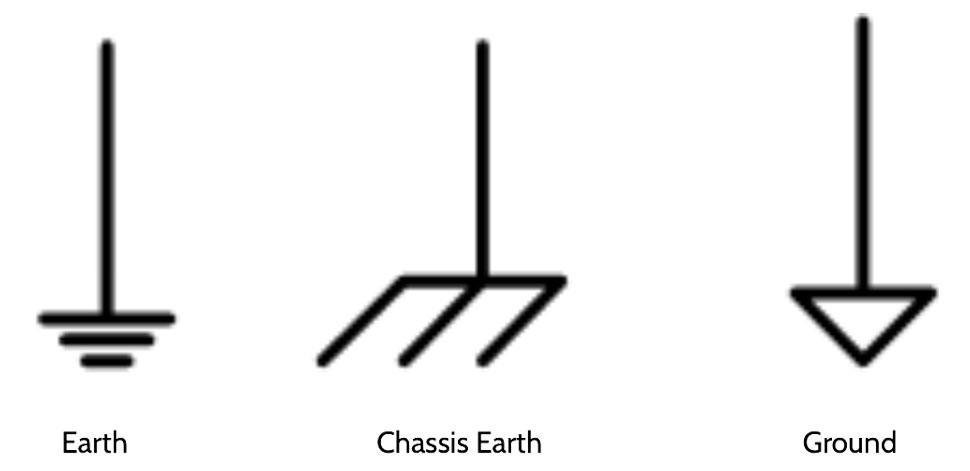
In regard to campervan electrical installations, there are 3 types of earthing worth noting, namely:
Earth is a direct connection via a copper cable to the Earth. This is achieved by a copper rod or copper tape driven into the ground. Depending on the building this could be a old water pipe or even a metal steel joist.
Chassis earth is a connection made to the metal work of a vehicle or boat. It could also be the electrical casing of large electrical equipment.
Ground is a common reference point in a circuit to which voltages are measured. As a result, a voltage may be above ground (positive) or below ground (negative).
What is the difference between earthing and bonding in our campervan’s electrical system?
Earthing and bonding are two distinct concepts used in electrical and safety systems, primarily to prevent electrical hazards and ensure the safety of individuals and equipment. They serve different purposes but are closely related.
Earthing (Grounding):
Purpose: Earthing, also known as grounding in the USA, is primarily intended to provide a safe path for electrical fault currents to dissipate into the earthing conductor, thereby preventing electrical shocks, fires, and equipment damage. For your campervans electrical installation you do not need to worry about earthing, this page purely exists to give understanding and context to the rest of the guide.
Function: It involves connecting metal parts of electrical equipment and systems (like appliances, electrical panels, machines, etc.) to the earth or a ground electrode (a metal rod buried in the ground).
Key Components: Grounding electrodes, grounding conductors, and grounding electrodes (ground rods, plates, etc.) are essential components of an earthing system.
Safety: Earthing ensures that if there is a fault in an electrical device, the current will flow into the ground instead of passing through people or objects, reducing the risk of electrical shock or fire.
I know what you’re thinking: how can we earth a campervan that sits on four rubber tyres? Well, if the van is
disconnected from the grid then its not technically ‘earthed’. In this instance we rely on the metal structure
of the van having enough mass to pull the electrical fault to the van chassis and trip the circuit breaker or
blow the fuse, there by disconnecting the supply.
That said, once we’ve connected our campervan to shore power either on a campsite or aire, the supply will
be ‘earthed’ by a copper rod connected to the Main Earthing Terminal of the hook up point that you plug into,
which will in turn ‘earth’ the campervan.
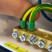
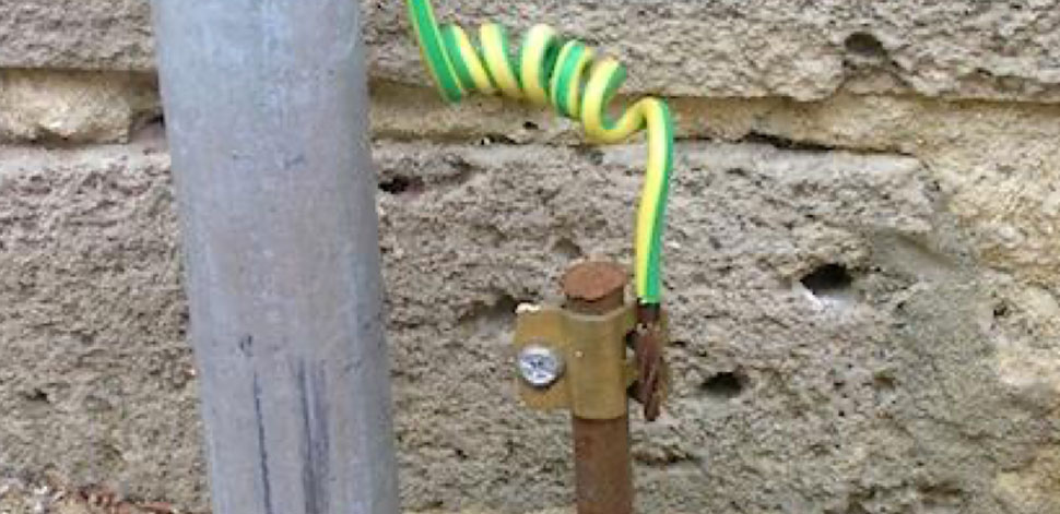 A copper rod buried into the ground creating a ‘earth’ or ‘ground’ connected to a motorhome hook up point via a green/yellow cable. You may see these on campsites or aires where you plug your campervan into shore power.
 What is bonding and why is it so important in our campervan’s electrical system?
Purpose: Bonding is primarily used to establish an electrical connection between various conductive components or structures which have the potential to become ‘live’.
Function: It involves connecting metal objects and structures together to ensure they are at the same electrical potential. This prevents differences in voltage between them, reducing the risk of electrical discharge, sparking, or static electricity buildup.
Key Components: Bonding conductors and clamps or connectors are used to create electrical connections between conductive materials.
Safety: Bonding is crucial in camper vans, motorhomes and boats. Every conductive parts needs to be bonded to achieve an ‘equipotential zone’.
Equipotential Zone: Equipotential zones are often used to create safe areas in electrical systems. Especially in AC systems. For example, the surface of a conducting material like the metal bodywork of a campervan can be an equipotential surface to prevent electric shocks to users. In such cases, any point on the casing has the same electric potential, so there is no potential difference to drive current through a person touching it.
A faraday cage is a great example of a equipotential zone.
Exposed conductive parts in a campervan’s electrical system
BS 7671 defines an exposed conductive part as a conductive part of equipment which can be touched and which is not normally live, but which can become live under fault conditions.
In essence, an exposed conductive part is any metallic part of an appliance or equipment accessible to touch and liable to become live if a fault occurs within that appliance or equipment. Such equipment in a campervan or motorhome includes metal consumer units, water heaters, and microwave ovens.
BS 7671 requires that all exposed conductive parts are ‘earthed.’ That is, they must be connected to the installation main earthing terminal, and this is achieved by ensuring a connection to each with a circuit protective conductor (technical term for an earth wire).
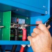
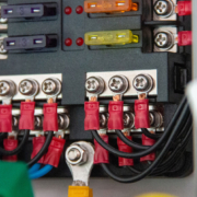
 A main earth terminal (MET) within a 230V distribution board housing two 4mm bonding cables. One chassis, the other for gas pipework.
Extraneous conductive parts in a camper vans electrical system
BS 7671 defines an extraneous conductive part as a conductive part liable to introduce a potential, generally earth potential, and not forming part of the electrical installation. In essence an extraneous conductive part is any metallic part entering the installation from the ground.
The parts considered extraneous in a campervan or motorhome are gas installation pipes and the chassis.
BS 7671 requires that all extraneous conductive parts are ‘bonded.’ That is, they must be connected to the installation main earthing terminal, and this is achieved by ensuring a connection to each with an ‘equipotential bonding conductor,’ or simply a protective bonding conductor.
Regulation 411.3.1.2 considers an extraneous-conductive-part as a conductive part liable to introduce ‘a dangerous potential difference’.


In a campervan, a chassis ground (often referred to as chassis earth) is a crucial electrical connection to ensure the safety and proper functioning of various electrical and electronic components. Here’s how it works in a campervan:
Principle: The concept of grounding is based on connecting various metal parts and electrical components of a vehicle to the vehicle’s chassis, which is typically made of metal. The chassis, in turn, is connected to the earth or ground through a thick, low-resistance wire.
Safety: Chassis grounding is primarily a safety feature. In the event of an electrical fault, such as a short circuit, the chassis ground provides a low-resistance path for electrical current to flow safely into the ground, operating the overcurrent protective device, reducing the risk of electrical shocks or fires.
Electrical System Reference: In a campervan’s electrical system, many devices and components require a reference point for voltage measurements and electrical potential. The chassis ground serves as this reference point. All electrical components are connected to the chassis ground to establish a common electrical reference.
To establish a proper chassis ground for your campervan’s electrical system:
- A dedicated wire is connected from a grounding point (typically a metal frame or body part) to a the main negative busbar of the DC system and main earth terminal of the 230V system. This bonds both the DC and AC system to the chassis of the campervan.
- Remember to remove the paint where you plan to make your connection, the paint will act as a insulator and may impede the connection.
- Some electrical components and devices within the campervan will need to have their metallic bodies connected to the chassis ground. Check the manufactures instructions to confirm which devices these are.
- Properly-sized wires and connectors should be used to ensure a low-resistance path for electrical current.
- Some devices require their metallic bodies to be grounded via their chassis ground terminal. For example a Victron Energy Multiplus Inverter Charger requires a dedicated cable to be ran from its metal work to the main negative busbar, which in turn is bonded to the chassis of the campervan. You will find all this information on our detailed wiring diagram (schematic).
 Our detailed Tiny Build Electrics wiring diagram showing a 16mm2 protective earth (PE) making its way to the main negative busbar.
 Keep in mind that the specifics of chassis grounding can vary depending on the vehicle’s make and model, as well as the electrical system design of the campervan. It’s essential to follow manufacturer guidelines and, if in doubt, consult with us at Tiny Build Electrics to ensure a safe and effective chassis grounding system in your campervan.
Neutral to Earth Link in Campervan Electrical Systems
An AC power source that’s feeding a campervan’s electrical system needs to have a neutral-to-earth link (MEN link) so that an Residual Current Device (RCD) can operate correctly. This is the case for the grid, but also if the AC source is a generator or an inverter.
But when combination inverter/charger units are used such has a Victron Energy Multiplus, the MEN link is less straightforward. The inverter/charger unit has two different modes of operation
 Earth relay open whilst connected to shore power.
 The inverter/charger is in charger mode and/or feed-through mode:
When the campervan electrical system is connected to shore power the AC input relay, within the inverter, is closed and at the same time, the earth relay is open (see diagram below).
The AC output system relies on the AC power supply to provide the neutral-to-earth link. This link is needed so the RCD in the AC output circuit is operational. Earth relay AC input relay.
Need help understanding how an RCD works?
 Earth relay closed when in inverter mode.
The Inverter/charger is in inverter mode:
When the shore power supply is disconnected from the campervan, or has tripped, the AC input relay opens. When the AC input relay is open, the installation does not have a neutral-to-earth link anymore.
This is why at the same time the earth relay is closed. As soon as the earth relay closes the inverter/charger has made an internal neutral-to-earth link. This link is needed so the RCD in the AC output circuit is operational.

FAQ’s
Do I need to bond the chassis of my van?
Yes. We need to bond every accessible conductive part of the vehicle so that they are of the
same potential. Our Tiny Build Electrics personalised wiring diagrams (schematics) clearly show each
bonding point to make it easy for the installer.
If a fault occurs and the fault current is sent to my van chassis, could this damage the vehicles
electronics?
Whilst we can’t guarantee that damage to vehicle electronics won’t take place under fault conditions, it’s
worth understanding that an electrical fault is better passing to the van chassis than via a human being to
earth which could result in injury or worse, death. The result of the fault being pulled to the van chassis
means the protective devices should trip or blow, disconnecting the supply and making the system safe.
Do I need to bond my chassis if I have a DC only system?
Yes. Irrespective of which system you decide to install, you must make every effort to bond the negative to
the chassis of your campervan. Our schematics make this very easy by showing you exactly what size cable
you require as well as exactly where the cables need terminating.
What if the body of my campervan or motorhome is fibreglass?
This is why we use the term ‘chassis ground’. The chassis of your vehicle will more than likely be steel, a
extraneous conductive part. Therefore every effort should be made to bond that part of the vehicle.
Do I need to bond my gas pipe to my main earth terminal?
BS 7671 – 721.411.3.1.2 Requires “that in each installation main protective bonding conductors complying with Chapter 54 shall connect to the main earthing terminal extraneous-conductive-parts including (ii) Gas installation pipes”
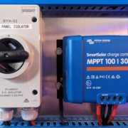
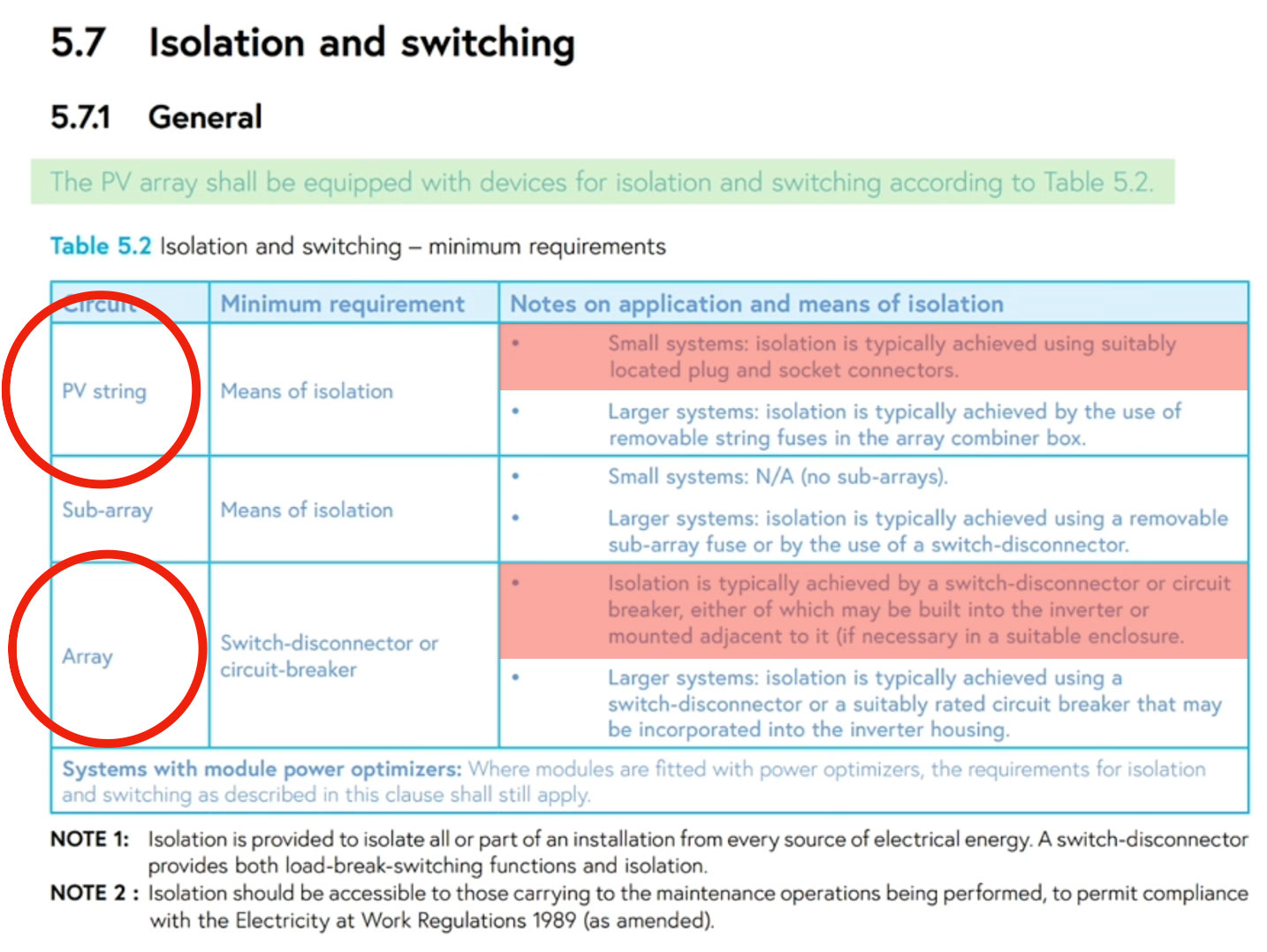
 A Solar Inverter with built in DC Isolator. Commonly used in Domestic applications.
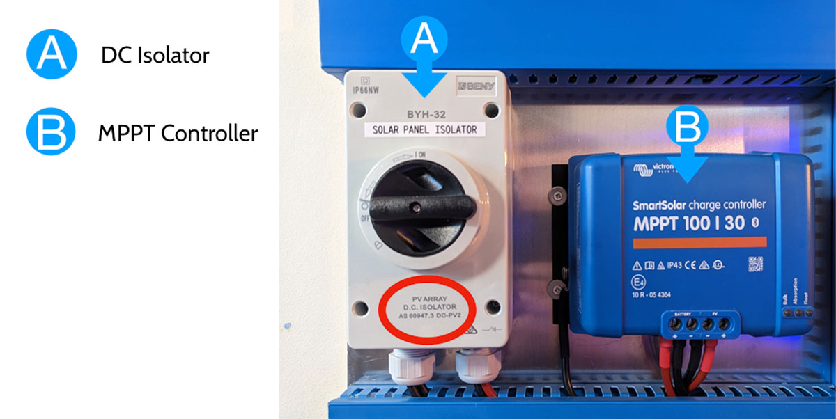 A Tiny Build Electrics installation using a DC Isolator, conforming to 60947-3, to isolate the solar panels from the rest of the installation.
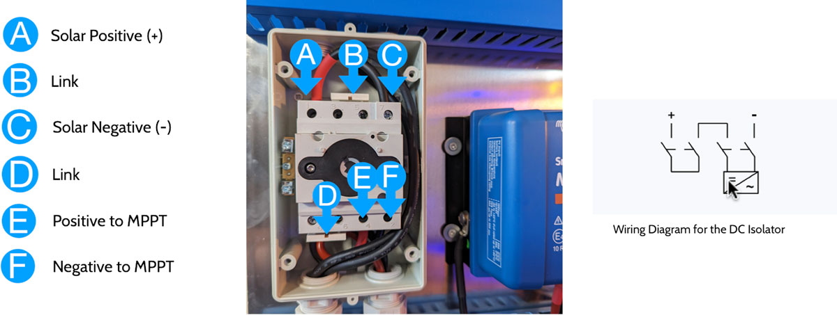 The inside of a DC isolator used to isolate solar panels in a campervan’s electrical system
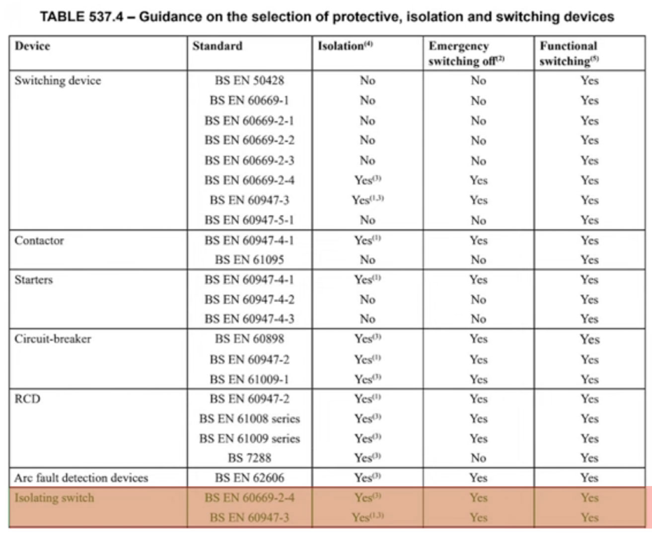

 Select correct size lug & cable
 Align lug with cable
 Strip insulation to match lug barrel
 Insert copper into lug
 Ensure crimper is set for the correct size lug
 Set crimper around the lug and compress
 Crimp as many more times as required
 Finish with heat shrink

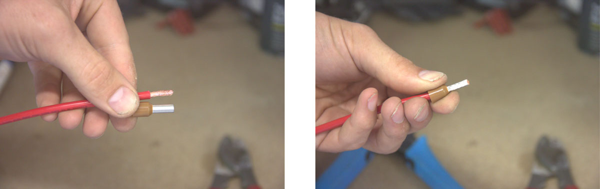
 Select correct size ferrule & cable
 Strip cable to the length of the ferrule barrel
 Locate cable inside ferrule barrel
 Select the correct size crimp and compress the ferrule
 Ensure the jaws are fully closed and tight around the barrel
 Give the ferrule and tug to ensure its tight around the copper
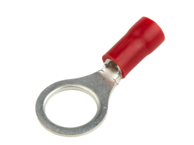
 Select correct size ring crimp & cable
 Strip cable to the length of the crimp barrel (allow 1-2mm more)
 Locate cable inside crimp barrel
 Select the correct size crimper and compress the crimp
 Ensure the jaws are fully closed and tight around the barrel
 Give the crimp and tug to ensure its tight around the copper