Carrying out basic campervan electrical testing is one of the most important stages of any van conversion. A few simple 12V DC safety checks can identify loose connections, poor terminations and dangerous faults before they become serious problems.
Quick answer
In short
Before you put your van into use, isolate every source of supply, lock the isolators off and prove the 12V system dead. Then work through four basic checks: a visual inspection, a tug test of every termination, labelling, and continuity. Every check is done dead, on the 12V DC side only. Leave all 230V inspection and testing to a qualified electrician.
- Isolate every supply, lock off, prove 0V
- Follow your wiring diagram like a flow chart
- Tug test every termination you have made
- Continuity: beep or low reading, end to end
On this page 7 sections
- In short
- Safe isolation of your campervan’s DC system
- Visually inspecting your campervan’s electrical installation
- Tug testing your campervan’s electrical system
- Identification of cables within your campervan’s electrical system
- Basic continuity testing of your campervan’s electrical system
- Summary: basic campervan electrical testing


Safe isolation of your campervan’s DC system
Every check in this guide is done on a dead system, so nothing here needs a live test. Leave the 230V side alone. Its inspection and testing is a job for a qualified electrician.
For the 12V side, you need a voltage tester or multimeter that reads DC volts. Its test leads should meet HSE guidance GS38: fused leads and shrouded probes with no more than 4mm of exposed tip. You also need your wiring diagram and a way to lock or tag each isolator off.

Isolate every source of supply
A campervan has more than one source of supply. Switch off each one before you start:
- Hook-up: unplug the lead at the bollard first, then at the van, and keep it with you.
- Inverter/charger: switch it off, so it can’t make 230V from the battery.
- Alternator charging: engine off and keys out, so the DC-DC charger has no input.
- Solar: switch off the PV isolator. The cable from the panels to the isolator stays live in daylight, so leave it alone.
- Battery: switch off the main battery isolator. The battery terminals, the battery fuse and the cable to the isolator stay live, so keep clear of them.
Next, lock or tag each isolator off, so nobody switches it back on while you work. If your van has no main battery isolator, have one fitted before going any further. In an emergency, you need to shut the whole system down quickly.
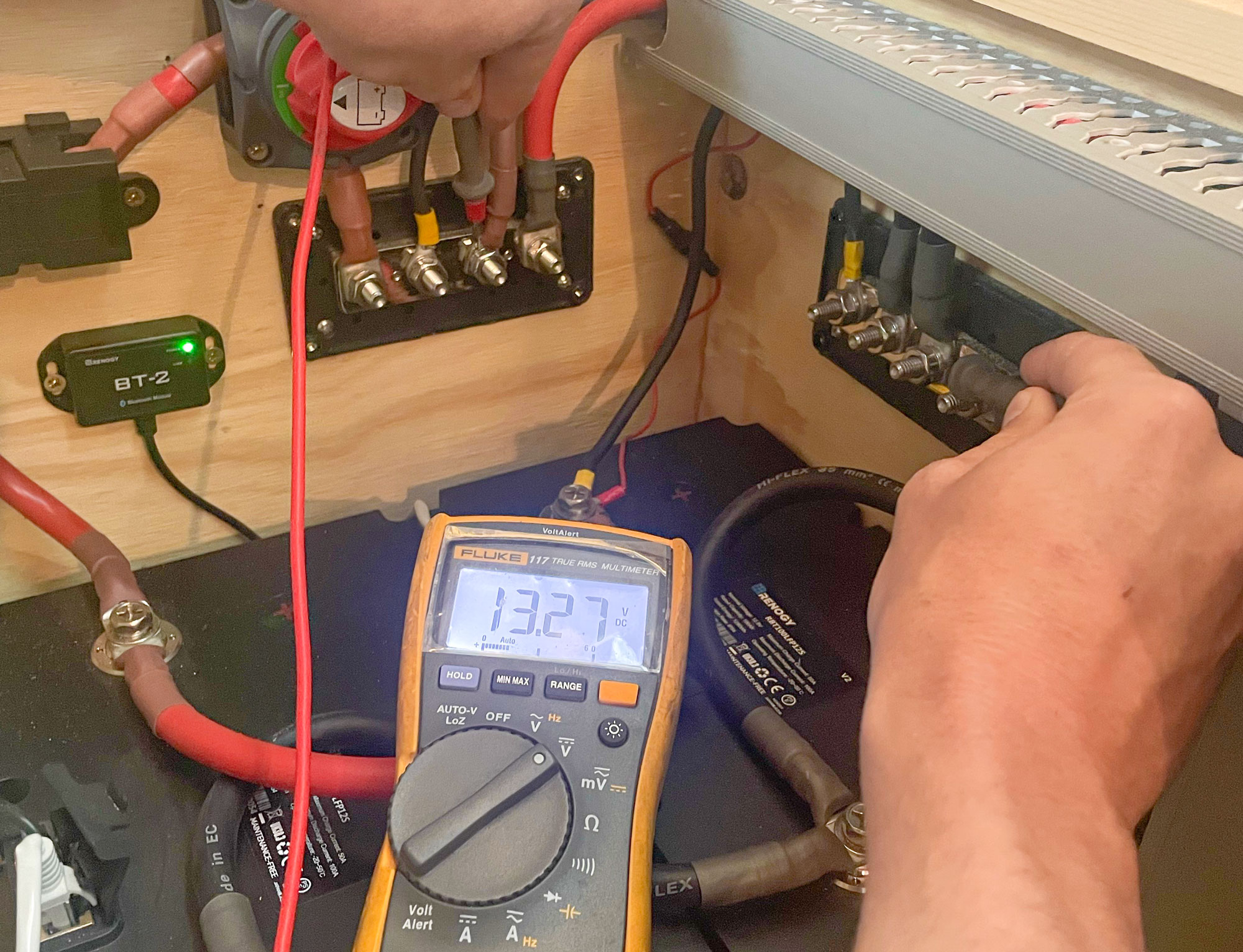
Prove the DC system dead before campervan electrical testing
A light that won’t switch on doesn’t prove the system is dead. Prove it with your tester, in three steps:
- Prove the tester. Check it reads correctly on a proving unit or another known 12V source.
- Test dead. Test between positive and negative on the dead side of each isolator. For example, test from the positive busbar to the negative busbar, then across the battery and PV terminals of the solar charge controller. Every reading should be 0V.
- Prove the tester again on the same known source, to confirm it didn’t fail during the test.
Only then is the system safely isolated. The isolators stay locked off until every check in this guide is finished.


Useful Definitions
-
System Voltage: The nominal voltage of the system as whole.
- PV Voltage: The voltage that your solar panels produce before the solar charge controller.
- PV Array: A linked collection of solar panel(s).
- Multimeters & Voltage Testers: Test equipment that measures voltage, used here to prove the system dead.
- GS38: HSE guidance on safe test probes and leads.
Visually inspecting your campervan’s electrical installation
A visual inspection is a crucial part of campervan electrical testing. Sit and run your eyes over the system. Think of the flow of electricity like water through pipes, and check that every cable runs correctly from A to B to C to D. This confirms the system is correctly connected. It also helps you understand how your system works.
This is also the stage to check against the wiring diagram (schematic) you used for the installation. Follow it like a flow chart. Make sure every device is in the right sequence, with the right cables running to and from it.
A visual inspection of your cable management is also a key aspect here. All cables should be secure and protected from external influences. Cable trunking is a good example of cable management. It protects the cable from damage, for example from surfboards and mountain bikes thrown in the back at the end of the day.
The trunking also gives the cables some air flow. That lets them dissipate heat and run within their design rating.
Next, check how cables enter enclosures such as control panels and jointing boxes. It is key to a system that lasts. Cables entering via sharp edges can cause potential damage to the cable over time. Here we must ensure that the cables are protected whilst the vehicle is moving and vibrating. Over time a sharp enclosure edge can slice into a cable and cause real problems. So give each one a quick wiggle, and check the gland or grommet holds the cable firm where it enters the enclosure.


Tug testing your campervan’s electrical system
If the cable pulls out during a tug test then it was never going to stand the test of time.
Tug testing is the most basic step in campervan electrical testing, but a critical one. Too many people skip it. Yet a simple tug on a cable would have revealed the loose connection behind many later faults. Tug every termination you have made. Yes, every single one: there are probably hundreds, but do it! Lugs are usually fixed with a nut and bolt, so a wiggle of the lug is enough.
Check that the lug is secure and makes a solid face to face connection. Also check that the copper is crimped tightly in the lug, with no strands poking out where the cable enters. On our builds, every connection is torqued to the maker’s figure and torque-pen marked.
Key areas for tug and wiggle testing are at the fuses and protection devices. A loose connection here causes a high resistance joint. That joint will ultimately pull a higher current, which can lead to arcing and potentially a fire.
You can also tug test through crimps, bootlace ferrules and the ever popular WAGOs. Remember, if a cable pulls out in a tug test, it was never going to last. Down those bumpy lanes to the best surf spot, these connections need to be solid. That is what tug testing is for. After all, you would rather find a loose connection now than miles from home.


Identification of cables within your campervan’s electrical system
Identifying your cables is a really good way of future proofing your installation.
Buy a labeller and label everything! You’ll be on your travels, an issue will arise and the labelling process that you undertook will save you hours.
Label all your DC circuits. Then you always know which cable supplies which piece of equipment.
You should also label every isolator. Knowing which isolator you’re turning is crucial. If your van sits for a period of time you may want to isolate certain aspects of the installation. This is a great way of knowing exactly what is isolated and what is not.
Labelling your individual fuses is also a must, this can save a whole lot of time fault finding another day. Knowing what part of the system has failed and then knowing where said components are is crucial to any installation.
Ensure your cable colours are correct. This is crucial in any good installation. Using a red colour for your DC positive and black for your DC negative is a good place to start. Some cables are plain black, such as the ones from your solar panels. In that case, label the positive and put a red band or heat shrink around the neck of the cable.


Basic continuity testing of your campervan’s electrical system
Once you are satisfied with your visual and tug testing, move on to some basic continuity testing. Keep the system isolated and proven dead. A continuity test on a live circuit gives false readings and can damage the meter.
Continuity testing is simply ensuring that the start of your cable is connected to the end of your cable.

For example, one cable starts at your battery or busbar (origin). It runs to your 12V DC distribution panel (load) to power your lights, fridge and fan.
That cable should be continuous: origin to fuse, fuse to isolator, then isolator to distribution panel.
Sounds obvious. However, by the end of the build your cable management covers these cables, and walls, kitchen cabinets and shower rooms hide the rest. You can no longer see them end to end.
How a continuity test works
Set your test equipment to continuity (see pictures below) and touch the probe ends together. You should hear a beep, see 0.00 ohms, or both (diagram above left). You are simply creating a loop. The meter sends a signal out on one probe, and the other probe returns it to the meter.


Remember: Lower number = Lower resistance & Higher number = Higher resistance
A continuity test does exactly that, but with the probes at each end of your cable. The cable becomes part of the loop. That proves it is continuous, with no breaks.
At this basic level of campervan electrical testing you are simply listening out for a beep or looking for a low value. Values vary with cable length and thickness, and with the fuses and switches in the circuit.
Every joint that you make adds a level of resistance the the circuit. That is what you are measuring with your test equipment. A thick cable with no joints gives the lowest reading. In contrast, a thin cable with plenty of joints, fuses and switches reads higher, because there are more obstacles in the way. That is what we call resistance.
You can run through a scenario with the diagram below.

Worked example of campervan electrical testing: busbar to lamp
First, touch one probe (it doesn’t matter which) on the positive busbar (1). If your system has no busbar, use the nearest positive terminal on the dead side of the isolator.
With that probe firmly on the busbar, put the other probe on the next connection in the diagram, at one end of the fuse (2). Here, if the cable is uninterrupted and continuous you should hear beep from your multimeter and, or a low reading.
You now know the cable between the busbar and the fuse is continuous.
Then test the fuse itself: one probe on each side of the fuse (2 and 3). Beep, or a low reading! This confirms to you that your fuse is intact and has not been broken or has blown.
Next, put a probe on the outgoing side of the fuse (3) and the other on the lamp’s positive connection (4). Beep, or a low reading!
You have now confirmed continuity from the busbar (the origin of the circuit) to the load (the end of the circuit). So current can flow freely along this route.
*Note, your test leads may not be long enough to reach end to end of every circuit. You can make a longer bit of cable which will help you reach other parts of the installation, this is known in the electrical industry as a wandering lead.
How many cables to test
*Not every cable needs a continuity test. It takes time, and if you can see a cable end to end, you can be sure it is whole and connected at both ends.
This is a really good way of proving you have good connections and your circuit is entire. If this is your first installation I recommend doing as many cables as you possibly can. If you are more experienced you can apply diversity factor and do a random selection.
Useful Definitions
-
Continuity testing: Used to establish whether an electrical circuit can be made between two points.
- Origin: The point or place where the electrical system begins. (Campervan leisure Batteries).
- Load: A device that consumes electrical energy. (Lights, fan, inverter, pump).
- Fuse: An electrical safety device having a metal wire or strip that melts and interrupts the circuit when the current becomes too strong.
- Busbar: A metallic strip or bar used to distribute electricity to several circuits from one location.

Summary: basic campervan electrical testing
We at Tiny Build Electrics believe the words “electrical testing” can seem daunting. You may think it involves complicated procedures and equipment, and it can. Even so, a few basic tests like these are far better than none. If your campervan electrical testing finds one slightly loose cable or a mislabelled fuse, it was worth it.
Visually testing, tug testing and carrying out basic levels of continuity testing does not need to be complicated nor scary. With these tests done, you can sleep soundly in your home on wheels, knowing the fundamentals are right.
Van conversion, boat, motorhome, log cabin or any other tiny build: you can apply these basic procedures to installations big and small!
*These checks cover the 12V DC side only. For your 230V system, contact a qualified electrician to inspect and test that part of the installation. Those tests need more complex equipment, and some are carried out live, so only a competent person should do them.
Campervan electrical testing FAQs
Can I test my own campervan electrics?
You can carry out basic checks on the 12V DC side with the system isolated and proved dead: a visual inspection, tug tests, labelling and continuity. Leave all 230V inspection and testing to a qualified electrician.
What should a continuity test read?
A beep, a low reading in ohms, or both. Fuses, switches and joints add a little resistance. An open circuit gives no beep and the meter shows over-range, often OL.
Do I need to continuity test every cable?
No. If you can see a cable from end to end, you can confirm it by eye. On a first build, test as many as you can. With more experience, test a random selection.
About the reviewer: Tom Alderdice
Tom holds the 18th Edition (BS 7671) and inspection and testing qualifications, plus NCC training in caravan and motorhome electrics.
Tiny Build Electrics is an Authorised Victron Energy Installer. See Tom’s full qualifications